Introduction
This document provides the steps to use in order to verify the operation of an Intrusion Prevention System (IPS) sensor and signature test options in a production environment.
Prerequisites
Requirements
There are no specific requirements for this document.
Components Used
The information in this document is based on these software versions:
- Intrusion Prevention System Release 6.2(x)E4
- Intrusion Prevention System Release 7.0(x)E4
- Intrusion Prevention System Release 7.1(x)E4
The information in this document was created from the devices in a specific lab environment. All of the devices used in this document started with a cleared (default) configuration. If your network is live, make sure that you understand the potential impact of any command.
Conventions
Refer to Cisco Technical Tips Conventions for more information on document conventions.
Internal, External and Management Communications
Use these steps in order to verify IPS management access and readiness:
- Access the console in the IPS. If this is a module issue, then enter:
- session 1 from the Adaptive Security Appliance (ASA) 5500 and 5585 series,
- session ips from a 5500x,
- service-module ids-sensor slot/port session on a Network Module Enhanced (NME) module,
- sessionslot_number in CatOS, and
- session slot module_number processor 1 in IOS for the Intrusion Detection System (IDSM) and IDSM-2 (second-generation) modules.
- Login with the username and password that was configured in the initial setup. The default username and password is "cisco". Refer to the setup guide for the appropriate release for more details.
- If the setup is already complete, then proceed to test IP connectivity to the IPS management.
- Enter the show statistics host command, and try to ping and obtain Secure Shell (SSH) access to the IPS management IP address. If this works, then continue to the next step. If not, then troubleshoot the connectivity problems with the configuration guide for the appropriate release.
- Enter the show version command. Verify the software version is current, that a license is installed, the signature version is the latest, all of the engines are operational, and that the host certificate is valid.
- If all of the previous steps are validated, then access the management address of the IPS via HTTPS and launch IDM. Java 6 must be installed. If Java 6 is not available, then install IPS Manager Express (IME) from the IPS web page.Note: Java 7 is not supported to launch IPS Device Manager (IDM) or to access IPS options in Adaptive Security Device Manager (ASDM) at this time.
- If connectivity is successful, then in the IDM, go to Configuration > Sensor Management > Licensing and Update License from Cisco.com. Even if a valid license exists, this confirms connectivity to the Internet.
- If successful, then go to Configuration > Policies > Global Correlation > Inspection/Reputation and click on Test Global Correlation to make sure the DNS works. In order to check this, go to Monitoring > Events and select only Warning, Error and Fatal and confirm if the Global Correlation updates fail.Note: Global Correlation is not available on IPS software earlier than IPS Release 7.0.
Verify Inspection of Traffic
After you verify communications through the IPS, you can verify inspection of traffic with these steps.
- Verify that the sensor sensing interface Link Status is Up and receives traffic. Login to the sensor interface and enter these commands:
sensor# show interface


!! In the output, find the applicable section for the sensing interface(s) in !! question and confirm that the Link Status value is "Up". If so, note the !! value shown for the Total Packets Received counter. After a few seconds, !! run the command again and compare the current value to the previous. !! If the value has increased, the sensing interface(s) in-question is Up !! and receiving traffic. Example:


sensor# show interface
MAC statistics from interface GigabitEthernet0/0
   Interface function = Sensing interface
   Link Status = Up
   Total Packets Received = 100

sensor# show interface
MAC statistics from interface GigabitEthernet0/0
   Interface function = Sensing interface
   Link Status = Up
   Total Packets Received = 150


!! If a sensing interface's Link Status value is expected to be "Up", but is !! not, verify that it is properly and physically connected to a switchport or !! other network device. If so, verify that the switchport or other network !! device is configured properly and the remote interface (the switchport or !! NIC on the other network device) is not administratively-disabled !! ("shutdown"). If needed, try to swap cables with another that is known !! to be good. !! If a sensing interface's Total Packets Received counter does not increment, !! check the configuration of the switchport or other network device to which !! the sensing interface is connected. If the sensing interface is supposed to !! be the destination of a SPAN/monitor session, verify the SPAN/monitor !! configuration on the switch the sensing interface is connected.
- Alternatively in IDM, verify all monitoring interfaces display a link value of up through Home > Interface Status.
- Verify that the sensor's virtual-sensor(s) has at least one sensing interface assigned and inspects traffic. Login to the sensor and enter this command.
 sensor# show stat virtual


!! In the output, find the List of interfaces monitored by this virtual !! sensor line and confirm that at least one (1) sensing interface(s) is !! listed. Additionally, find the Total packets processed since reset !! line/counter and confirm its value is greater-than (>) zero (0). !! Example:


sensor# show stat virtual
   Statistics for Virtual Sensor vs0
      List of interfaces monitored by this virtual sensor = GigabitEthernet0/0
      General Statistics for this Virtual Sensor
         Total packets processed since reset = 200


!! If there are no sensing interface(s) listed (or, if additional sensing !! interfaces need to be assigned), login to the sensor using an !! administrative account and issue the following commands !! (NOTE: In the example provided, the GigabitEthernet0/0 sensing interface !! is assigned to virtual-sensor vs0. Replace that particular configuration !! line accordingly with the actual sensing interface you wish to assign to !! the virtual-sensor. If you need to assign multiple sensing interfaces, !! repeat that line (one per sensing interface)):


sensor# conf t
sensor(config) # service analysis-engine
sensor(config-ana) # virtual-sensor vs0
sensor(config-ana-vir)# physical-interface GigabitEthernet0/0
sensor(config-ana-vir)# exit
sensor(config-ana)# exit
Apply Changes?[yes]: yes


!! NOTE: The above example assigns a Promiscuous sensing interface to the vs0 !! virtual-sensor. Inline sensing interfaces must first be "paired" together !! and then the logical pair assigned to a virtual-sensor. Details can be !! found in the official product configuration guide's Configuring !! Interfaces section.
- Alternatively, verify that interfaces are assigned to vs0 in IDM under Configuration > Policies > IPS Policies.
- Enter SSH to the IPS and enter the packet display interface slot/port command and verify traffic is seen on the interface.Note: The expression keyword allows the use of tcpdump expressions in order to display only traffic which matches the expression used.
sensor# packet display gigabitEthernet0/1 expression ip host 198.51.100.1
Warning: This command will cause significant performance degradation
tcpdump: WARNING: ge0_1: no IPv4 address assigned
tcpdump: verbose output suppressed, use -v or -vv for full protocol decode
listening on ge0_1, link-type EN10MB (Ethernet), capture size 65535 bytes
18:32:24.247864 IP 198.51.100.1.2000 > 192.0.2.1.2000: UDP, length 172
18:32:24.247868 IP 198.51.100.1.2000 > 192.0.2.1.2000: UDP, length 172
18:32:24.257249 IP 198.51.100.1.2000 > 192.0.2.1.16384: UDP, length 172


!! Alternatively, in the case of VLAN tagging:


sensor# packet display gigabitEthernet0/1 expression vlan 20 and
    ip host 192.51.100.1


Verify Signature Fires
- Signature events can be viewed in the Monitoring section.
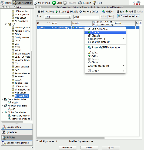
- Signatures can be modified under Configuration > All Signatures.
- Enable signatures 2000/0 and 2004/0 (Internet Control Message Protocol (ICMP) Echo Reply and ICMP Echo Request); initiate a ping through the sensor, and check the event log at the Monitoring tab.If the ICMP is blocked:For 1107/0, refer to RFC1918 - Address Seen.
- In order to trigger this signature, set retire to false and enable to true on this signature and watch the IPs in the RFC 1918 ranges trigger the signatures.
- These addresses are 10.0.0.0/8, 172.16.0.0-172.31.255.255, 192.168.0.0/16.
- This cannot be seen on an SSC-5 because it is required for the signature to be unretired.
For 3409/0, telnet to port 80.- With web server setup, port 80 is open and telnet is successful. When the telnet is successful, the event fires on the IPS.
- A TCP 3-way handshake is required in order for the sensor to track the valid TCP connection. In the case of asymmetric routing or a replay of a partial packet capture, the traffic does not cause a fire of the signature.
After testing is complete, restore the defaults to any modified signatures:


No comments:
Post a Comment